This is one of several posts regarding Polar Modulation, the first being here.
In this post I will be digging further into the phase calculations that were introduced earlier.
Where we left off last time, we had talked about how the incoming audio signal can be represented as a phasor, and that the Hilbert Transform generates I and Q signals that represent that phasor.

The phase and magnitude of the waveform can be derived from these I, Q signals:
amplitude = sqrt(I*I, Q*Q)
phase = atan2(Q, I)
We also raised the need to perform Phase Unwrapping, which is caused by the atan2() function only giving a value between -π and +π:
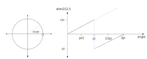
To correctly calculate the phase difference between two successive measurements phase unwrapping must be taken into account. The solution discussed previously was to perform two checks on the phase difference:
if (deltaPhase < 0) deltaPhase = deltaPhase + 2*PI // phase unwrapping
if (deltaPhase >PI) deltaPhase = deltaPhase - 2*PI // phase unwrapping
Even with these calculations, both the simulation and real hardware still exhibit some low level spuri. I already knew that the phase calculations were important, and that adding the second line above made a huge difference under some circumstances. I therefore wondered whether some errors in the delta phase calculations still remained, and whether some improvements to the delta phase calculations could be made.
I started to investigate when exactly the atan2() discontinuity would occur, and whether the phase calculation above were correct under all circumstances. My alternative approach was to consider drawing a line between successive measurements in phase space:
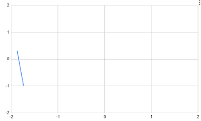
I argued that if the line crosses the negative x axis (as in the diagram above), then the atan2() discontinuity would arise, and the delta phase calculation should take the 2π change into account. Adding or subtracting 2π depends on whether the x axis is crossed from below or from above.

The prior measurement is 5° at most, and the latest measurement is about -110°. The delta phase calculation is therefore -110° - 5° = -105°.

- The step from orange to purple, and from purple to red, are very dramatic negative phase changes.
- Very slightly increasing the amplitude of the higher frequency tone causes the result phasor to pass very close to, but now slightly above, the origin, resulting in dramatic positive phase changes.
This is a most interesting result. A tiny change in the amplitude of the higher frequency tone results in a dramatically different phase difference calculation. But the consequence on the generated signal are tiny - the difference in the output spectrum is tiny and corresponds exactly to the input amplitude change. This is despite one output signal having a brief negative frequency blip, and the other having a brief positive frequency blip.
The key conclusion we can draw is that it is the resulting phase shift that is important, and that the specific output frequencies are just to accomplish this phase shift. A desired phase shift can be accomplished by either temporarily speeding up or slowing down the output frequency. And this is what's happening here - in one case the approximately 180° phase shift is accomplished by increasing the frequency, and in the other case by decreasing the frequency. The mathematics is such that the "shortest path" is taken to move from one phase to the next. A longer path (i.e. a rotation in the opposite direction) could be taken, but that would require a higher frequency output.
This insight into the importance of phase rather than frequency helps reconcile the different results produced by the line crossing algorithm and the simple algorithm. They both give a "correct" phase difference - it's just that one result takes "the long way around", and the other gives the "shortest path". This explains why both algorithms gave similar results.
This insight also gives us a way to derive a good phase difference: first calculate the raw phase difference and then calculate the shortest path - if the angle is more than π/180°, go around the other way:
if (deltaPhase <-PI) deltaPhase = deltaPhase + 2*PI // take the shorter pathif (deltaPhase > PI) deltaPhase = deltaPhase - 2*PI // take the shorter path
This "shortest path" algorithm simultaneously addresses the atan2() discontinuity.
The "shortest path" algorithm has been tested both in the simulator and on test hardware, and all results are no worse than the original algorithm at the top of this page.
Conclusion
This discussion has led to some insights into the importance of phase, and the relative unimportance of the direction of frequency change. A new "shortest path" algorithm has been derived and has the benefit of some solid thinking behind it. I now have much more confidence that this is the best the algorithm can be, and that the remaining spuri are for other reasons.