I'm using the Si5351 programable clock generator in an upcoming project, portions of which are similar to the usdx. For my application, characteristics of the chip that are important, but not documented in the datasheet, are:
- When does the output frequency change in relation to the I2C command that has been issued to update the frequency? Answer: on the second to last low-to-high I2C clock transition of the command that writes the lowest byte of the PLL register.
- How long does the output frequency take to reach the target frequency (its settling time)? Answer: < 1us! Yes, it settles extremely quickly.
This note describes how I measured these characteristics.
For my tests, the Si5351's output frequency is being updated at up to 12k times per second. The I2C bus is overclocked at 800kHz to achieve this update rate. The usdx project implements a frequency-change mechanism where just 5 on-chip 8-bit register values are updated in a single I2S 7 byte transaction. The update is made to alter the PLL frequency. For the purposes of my tests I use the same mechanism, but only need to update 4 registers for the range of frequency changes I'm conducting. Documenting the exact frequency update mechanism is outside the scope of this note, but can be ascertained from the usdx code and reference to AN619.
Note that my tests also showed that the Si5351 output only changes when the lowest byte of
Test Method
I used a mixer to compare the Si5351's output target frequency against a known reference frequency. The filtered mixer's output is the difference between the input frequencies. So when the two frequencies are the same, or very similar, the output is either constant or changes only slowly. I initially used a filter RC time constant of 1us.
The mixer was built from a 3253 analogue switch. The mixer is very much like a quarter of a Tayloe Mixer.
The fixed frequency could be provided by an external source, but in my case I used a second Si5351 output. I have relied on the fact that the si5351 can be configured to output 2 frequencies completely independently - each with their own PLL and MultiSynth divider chain (a third output frequency can also be configured, but must share one of the PLLs):
- the target frequency on CLK1 whose frequency will be adjusted by ±4kHz (or more).
- the reference frequency on CLK2 whose frequency is locked and stable throughout a test.

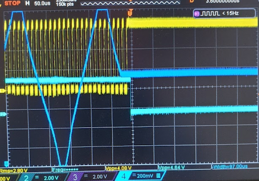
(where yellow = I2C clock, cyan = digital output, blue = mixer output).


The frequency transition occurs within 1us.
No comments:
Post a Comment